- PCB board revision 1.4
- Custom firmware revision 3.2
Sensor in standard case
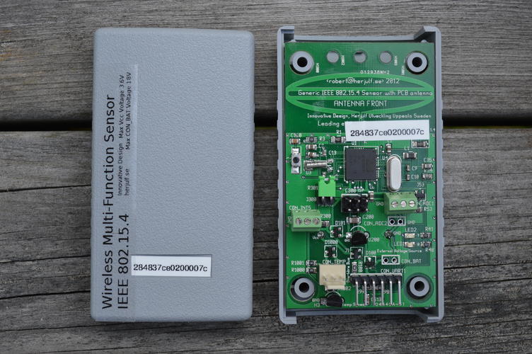
The sensor board suitable for data collection, monitoring and "Internet of things" (IoT) type applications. MCU can be used with Contiki, TinyOs and other operating systems. Board is preprogrammed with versatile and easy to use custom firmware, based on Contiki Rime broadcast protocol. The radio coverage (following the IEEE 802.15.4 output power 3 mW) using the built-in PCB antenna is 300 meter line-of-sight. (LOS) PCB is designed for a IP54 classed standard case but of course enclosures are possible.
A very minimal wireless network
An absolute minimal usable wireless network needs:
- Two sensor/motes
- One FTDI 3.3V USB-TTL-cable. (TTL with 6 pin header)
Hardware description
- MCU AtMega128rfa1 with integrated IEEE 802.15.4 Transceiver.
- Integrated High-Performance PCB antenna. Supercardiod.
- Low-Power Voltage regulator for wide voltage input range.
- Direct power option. Max 3.6V bypassing the voltage reg.
- Hi-res 12 bit temp. sensor.
- Unique 64 bit ID via temp. sensor.
- 2 Analog inputs. ADC1/AD1, ADC2/AD2
- 1 Analog input to voltage regulator. CON_BAT/V_IN
- 1 GPIO/pulse pin. with jumper. selectable pull-up. P0.
- 1 Programmable power pin Vcc. via FET for external sensor.
- 1 GPIO with connector intended for one-wire bus.
- 2 LED's Red/Yellow for monitoring and debugging.
- Programmable via AVR 6-Pin (0.1"") ISP or via USB/serial bootloader.
- Compact size. PCB 80x45.5 mm. Case 90x50x32 mm standard case.
- Weight 20 gr without battery and holder including standard case 70 gr
- Optional on-board humidity sensor. Honeywell, Hih6130/Hih6131
- Optional on-board comparator typical use w. 0805 or 1206 phototrans. P1
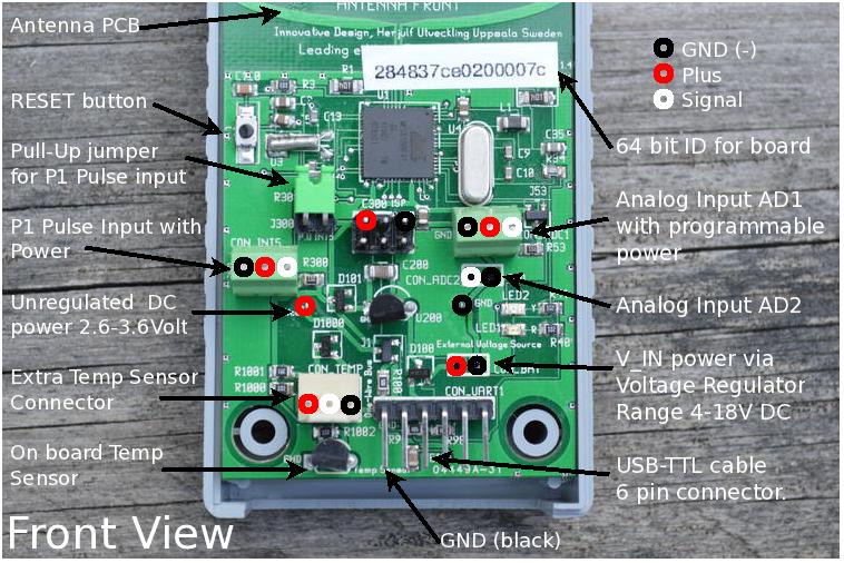
PCB front view
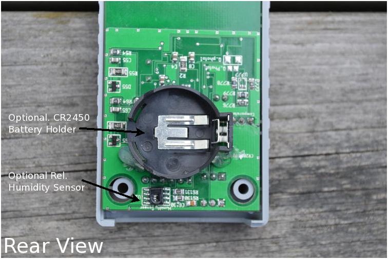
PCB rear view
Quick start for the impatient
You'll need two or more nodes and a USB-TTL cable you're also set with the default settings.
- Connect one node to your computers terminal program via the USB-TTL cable
- Power the other node(s) with battery or use any other option.
Terminal programs include, minicom, hyperterminal. Baud 38400 bps, 1 stopbit no parity, no flow-control. The node connected to USB will also be powered from USB and will automatically report data from it's neighboring nodes.
Power options
External power options
- USB power. Using the USB-TTL cable with 6 pin header at bottom.
- Parasite power via voltage regulator. Marked CON_BAT. 3.5-18 Volt.
Battery power options
Via the regulated input through voltage regulator via CON_BAT.- 6/12V lead acid or similar to CON_BAT.
- Lithium-ion 4.2V to CON_BAT.
- Coin Cell battery Lithium 3V CR2450 or similar via battery holder on back of PCB
- 2 Pcs in serial 3V AA or AAA alkaline batteries.
- 1 Pcs Lithium-thionyl chloride battery 3.6V (AA, AAA and other footprints)
- 1 Pcs LiFePO4 battery 3.3V (AA, AAA and other footprints)
- 2 Pcs in serial NiMH 2.8V
- CAUTION! Be aware that voltage above 3.6V will permanently damage your mote.
Sink node or receiving node
A receiving node (sink) is node that reports it's incoming data packets (reports) from neighboring nodes. The reports are sent over USB. With the custom firmware a sensor/mote automatically becomes a sink node when the USB-TTL cable is attached.
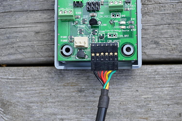
PCB USB-cable TTL-USB 6-pin connector.
To create a USB capable a device a FTDI USB-TTL cable is needed. The cable has a standard type-A USB connector for host side. The sensor/mote side uses a 6 pin connector. See picture for how to connect. When cable is connected to USB sensor get powered via USB. NOTE the custom firmware detects USB power and turns mote into a sink mote by turning radio on and reporting received data via USB.
NOTE. Disconnect the 6-pin header from sensor/mote when cable is not connected to any host as the cable forces the MCU use much more power.
Battery lifetime
Battery lifetime is a crucial and challanging area. It's dependent on number of different factors among them:
- How the radio is used. Number of transmits, see report interval.
- Radio Duty Cycling (RDC).
- How MCU uses sleep modes.
- Sensors current consumption.
- Battery type.
- Temperature.
- Self discharge
- Battery discharge function.
- 10 uA MCU PWR_SAVE Radio OFF
- 3 mA MCU IDLE Radio OFF
- 18 mA MCU Radio TX
Tips for debugging radio connectivity
Here you have to experiment a bit which a part of the WSN-life. Radio coverage at line-of-sight (LOS) is about 300 m this with the PCB antennas oriented. But walls and other hinders you have to test. For your help the custom firmware has functions to help examine you the radio coverage.
- Using radio reports coming on the USB interface.
- Using LED's on the PCB.
You can use the debug function in firmware to flash LED's when packets are received or transmitted. It's possible to walk around and check radio coverage checking the RX LED. Set the report interval (ri in firmware) to about 10s and enable debug (de in firmware with the mask for D_RX) to blink every RX-packet and move around and verify blinking and radio coverage.
It is also be useful to monitor RSSI/LQI via plots etc to understand the radio environment in detail for seasonal and other changes.
Data collection and monitoring
Net topology
Broadcast network
Custom firmware implements a broadcast network currently using Contiki Rime with radio reports in plain ASCII text. The data is formatted with tag-style encoding. Both address and report should fit in one IEEE 802.15.4 packet of 127 bytes. So any mote following this scheme can be a part of the network. Although one must make sure there are no address collisions. The the PCB has a unique 64-bit ID via the temperature sensor and automatically creates a unique Rime address based on this. As a single-hop-radio coverage a broadcast network is simple and attractive and useful for many applications.
The advantages:- Very simple setup.
- Very low power consumption.
- Robust.
- One-hop coverage.
- Sink nodes has radio on. High power consumption.
Each node is independent, MCU can be in very deep sleep mode and be woken up by interrupt timer and read the sensors form a data report and broadcast. The schema requires one or several sink nodes with full listening. They consume much more power. The sink receives the received data and form a URI and optionally store data in a file for later plotting and processing. There is no retransmission of broadcast packets. It's suggested to monitor packet sequential numbers for losses as well as RSSI and LQI for received packets.
sensd code and unix version
Sensd is a daemon to collect and visualize data from the WSN. send uses the USB connection to the sink node.
- URI (needs a web-server)
- datafile for plotting storage etc
URI examples
sensd can display the received data in hierarchical file tree intended to form an URI (Uniform resource identifier) for Internet access the file tree needs a web-sever to form the full URI. The URI format an easy-to-use and consistent way of accessing sensor data and align close to emerging IoT.
- From a solar driven node in the authors apple tree w. temp, humidity etc.
-
- http://www.herjulf.se/projects/sensor/WSN1-GW1/apple-tree/T
- Full apple-tree node URI's can be seen via:
-
- http://www.herjulf.se/projects/sensor/WSN1-GW1/apple-tree/
- Another node is monitoring UPS battery voltage:
-
- http://www.herjulf.se/projects/sensor/WSN1-GW1/UPS-battery-attic/V_IN
A plot and some more info are among Project Examples
- Another node is in a long term test for waster level/soil moisture:
-
- http://www.herjulf.se/projects/sensor/WSN1-GW1/soil-moisture/V_A1
The analog voltage is to be converted to the correct water level or soil moisture.
- Another node at house main power meter and reads the S0 interface:
-
- http://www.herjulf.se/projects/sensor/WSN1-GW1/main-AC-power/P0_T
Number of inpulses per secound. To be scaled to kW. See Project Examples.
NOTE. The combination sensd and a broadcast network does not give a REST'ful service (client-server) rather we get a caching server. Where we see data from the last received report.
sensd on windows
There is a first port to Windows. More info will come.
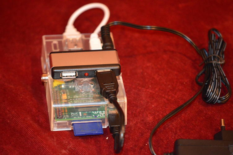
sensd on RPi
Small, cheap and powerful SoC platforms. Raspberry Pi is one who received a lot of attention. send builds nicely and runs but there have been some stops which are currently under investigation. Anyhow it's seems important to have sufficient and reliable power for both powering the device as to have externally powered USB-hub. Seems like the USB-TTL cable was able to reboot the RPi.
Custom firmware
The custom firmware controls the setting of the node, all settings are stored the non-volatile memory EEPROM of the MCU. Operational-, status-information, statistics and errors can be viewed via the firmware. On sink nodes all radio report from neighbors are seen via the firmware this is also where the sensd daemon gather it's information. Much design and programming has been focused to debug and troubleshoot the WSN network and the sensors.
Custom firmware: commands
There are many commands. Luckily you wont need most them but there are couple of commands that most users probably would like to use. First when using the firmware commands you have to connect to minicom, hyperterminal or similar terminal program via the USB-TTL cable. (38400 1 stop bit and no parity and no flow-control)
Basic commands
- Report interval. ri (how often)
- Report mask. re (what)
- System summary. ss
- h - help
- v - version
- u - uptime
- aes [on|off] - integrety
- For test only.
- cali [[a1|a2|v_in] voltage] - calibrate
- Calibrate the analog readings from v_in, ADC1, ADC2. Volt.
- No argument just prints the current reads. v_in, ADC1, ADC2
- de [mask] - debug
- Enable debug. See separate section.
- hum - humidity sensor
- Read (optional) humidity sensor..
- hump [on|off] - humidity perm sensor pwr
- On. For normal operation.
- id [reset] - id handling
- Print unique 64 bit ID.
- mcu - mcu info
- MCU related debugging info for non-mortals
- ne [flush] - neighbor table
- List of neighboring nodes. Addr, last SEQ, RSSI and LQI.
- Can be useful in monitoring the network.
- Cache can be flushed. New entries are created automatically.
- Entries older than 200 seconds are removed.
- log [auto|on|off] - motes data on USB
- Override the automatic log. setting.
- Which starts printing on USB when you connect the USB-TTL cable.
- ow - one-wire sensors
- The temperature sensors. Onboard and optional..
- re [mask] - mote report setting
- Report mask. See separate section.
- ri [int] - report interval
- Report interval in seconds. How often the node broadcast it's data.
- rs - radio stats
- Radio stats from Contiki. Contiki docs for details
- ss - system summary
- System summary. A collection of major setting
- pwr1 [on|off] - pin1 pwr
- To manually interfere with the programmable power on ADC1
- Programmable power is used to enable a sensor just before reading. To save power.
- If used. It's recommended you use this together with corresponding debugging LED D_PWR1.
- rest - restore eeprom
- Revert settings to factory default. Typically after firmware upgrade.
- boot - reboot
- Restart the node
- upgr - reboot via bootloader
- Restart the node but wait in boot loader
Custom firmware: report mask
Report is a bitmask. It set by the re command in firmware it crucial and control what data is used and sends from the node. re command without any argument prints the current setting. Stored in non-volatile EEPROM.NOTE! due to limited size (127 bytes) of IEEE 802.15.4 packets is recommended to keep report short. For trouble shooting see de D_OPER and err command.
- R_ID - The unique 64 bit ID HEX
- R_T_MCU - MCU internal temperature in Celsius
- R_V_MCU - MCU voltage. Volt.
- R_P0 - Total numbers of interrupts on P0 input. HEX. 32 bit.
- R_P0_T - P0 number Interrupts per second last during last report interval. Decimal.
- R_P1 - Total numbers of interrupts on P1 input. HEX. 32 bit.
- R_P1_T - P1 number Interrupts per second last during last report interval. Decimal.
- R_UPTIME - Number of seconds since node started. HEX.
- R_RH - Relative humidity in percent. Decimal.
- R_V_IN - Input voltage on regulated power input. Decimal
- R_A1 - Input voltage on ADC1 input. Volt. Decimal
- R_A2 - Input voltage on ADC2 input. Volt. Decimal
Custom firmware: debug commands
Debug is a bitmask. It is set by the de command in firmware. Several debug functions can be active concurrently. de command expects a HEX value. de command without any bitmask prints the current setting.
NOTE. That the debug setting is stored in EEPROM so rebooting restores the previous setting. Debug functions:- Indication via a LED
- Printout via USB.
- D_OPER
- Prints out if report exceeds packet payload.
- D_RX
- When packed is received. Flashes the red LED and forces at print out.
- D_TX
- When a packet is sent. Flashes the yellow LED and forces at print out.
- D_PKT
- Not used
- D_OW
- Not used
- D_LED
- LED test turn Red and Yellow LED On.
- D_POWER
- Not used
- D_EVENT
- When a neighbor is removed due to garbage collection.
- D_P0_LED
- Flashes the red LED for pulse on input P0
- D_P1_LED
- Flashes the yellow LED for pulse on input P1
- D_AES
- Prints the AES key when sending a packet.
- D_PWR_1
- Programmable power. Turns the red LED on when PWR1 on.
Custom firmware: firmware upgrade, flashing
firmware upgrade, flashing
It's possible to use the built-in bootloader to use the node with other firmware and operating systems. With the built-in bootloader one can simply use flash new code via the USB-TTL cable. A typical use would be:
See the section with HOWTO's for a more detailed information.
Programming: Pin assignments
- http://herjulf.se/products/WSN/sensors/documentation/HOWTO.pin_assignment_v1.4.h
See the section with HOWTO's for a more detailed information.
Contiki Platform Support
Atmega128rfa1 is a supported CPU in Contiki used in several board/platforms. There are patches to support this board. Current work i maintained by Petter Skiden and hosted in github. Platform is named avr-pluto. Platform has sample application for Rime broadcast.
Outdoor usage
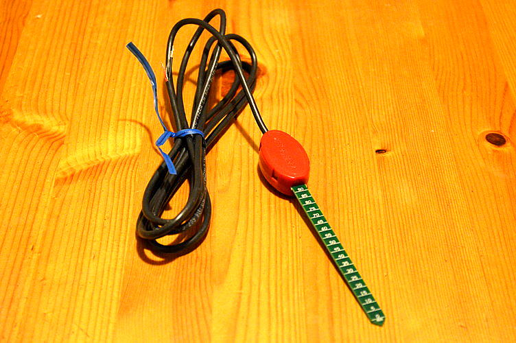
External temp sensors
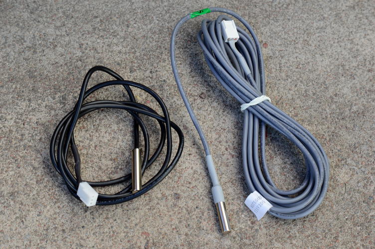
Picture shows two external temp. sensors The right sensor is waterproof and should be able to use for water and soil temperature measurements. Sensors are connected to PCB connector at posistion CON_TEMP. The temp. sensors uses external power via the the builtin cable for maximum robustness.
Hardware hacking
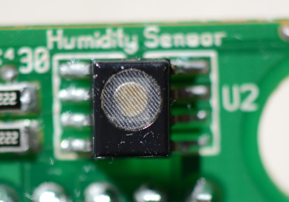
Hardware hacking: Humidity sensor
The humidity sensor is expensive double the MCU price. For that reason the sensor is optional. It's recommended that you get the board with the humidity sensor if you intend to used it. Nevertheless it's possible for people capable of SMD soldering but the device is fragile. So you're on your own. Temperature 270C for some second. You should also clean the PCB from old tin using a desoldering wick. The design is currently using the Honeywell Hih6130/6131 sensors. The Hih6131 has membrane and is considered as non-condensing.
Solar driven I. using NiMH
Some installations have successfully used two NiMH batteries in series connected to the unregulated input Vcc-GND. The charging voltage for a NiMH is about 1.42V with two in series 2.84V. The MCU voltage when power via CON_BAT or via USB is slightly above 3V. This violates the MiNh a bit but it seems to be working well. We have this deployed in SGN (Serengeti Broadband Network) in Tanzania. [SBN]
- Two NiMH cells in series at the unregulated input
- Solar panel to CON_BAT the regulated input. Voltage 3.5 - 5V.
Hardware hacking: Solar driven II using LiFePO4
In some installations 3.3V or higher voltage is needed. This is the case for the soil moisture sensors we're using. It's with some hardware modification possible to increase the the MCU voltage to 3.6V (the maximum MCU voltage). The charging voltage for LiFePO4 is just 3.6V.
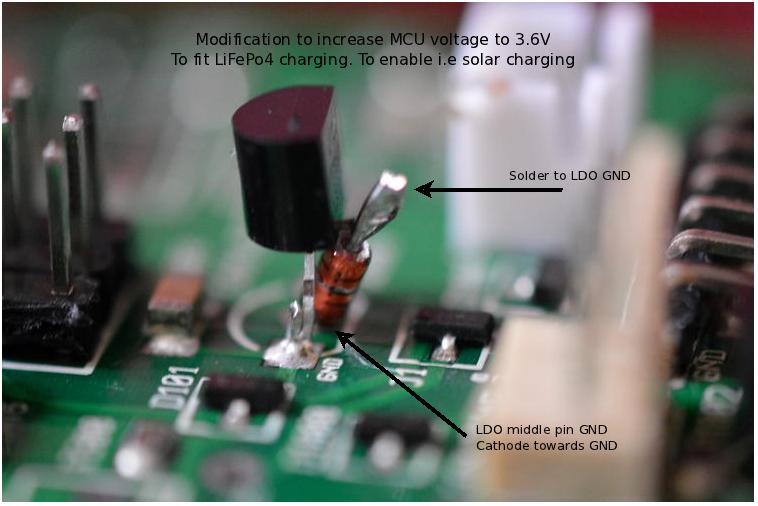
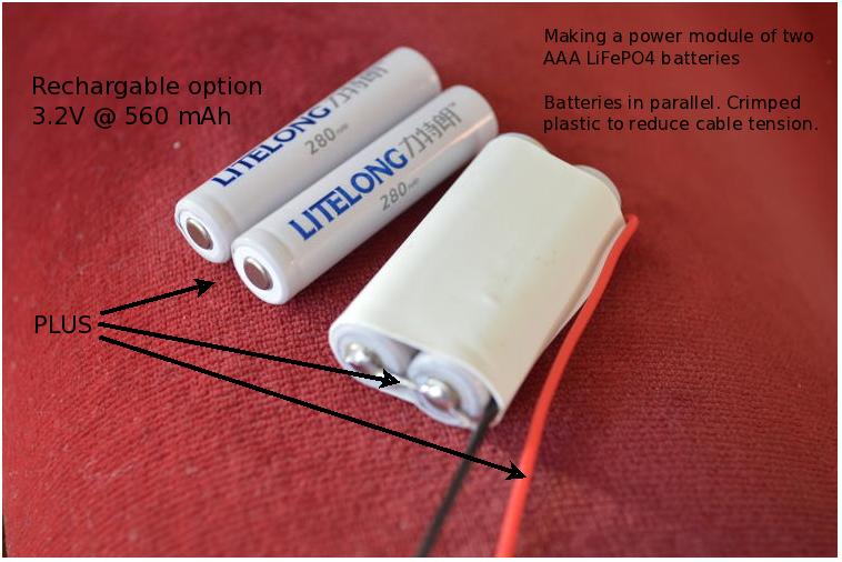
- One LiFePO4 at the unregulated input
- Solar panel to CON_BAT the regulated input. Voltage 3.5 - 5V.
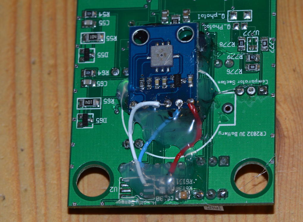
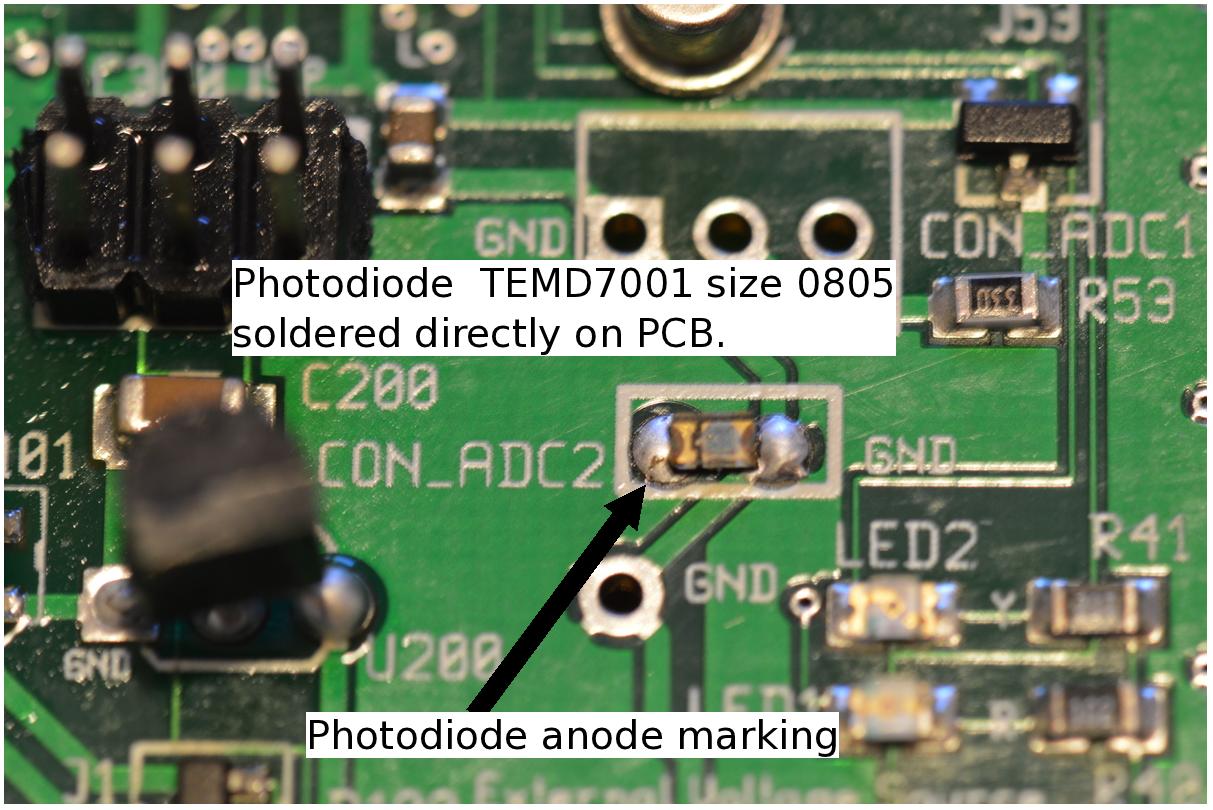
Hardware hacking: Comparator and phototransistor
This for hardened hardware geeks only. The pulse input P1 is connected to an optional comparator on the rear side of the PCB. Silk name is U777. The footprint is very hard to handle. But it's possible to mount for SMD skilled personal. Be sure to clean the footprint with desolder wick before soldering. Close to the comparator there are to footprints for phototransistors 1206 or 0806 footprints. The author soldered two thin wires to a small PCB with the photo transistor. The main reason to read the energy meter. Luckily the provider Vattenfall has offered an S0 interface. See the HOWTO section for more info.
Project and Examples
Project and Examples: Water level/soil moisture
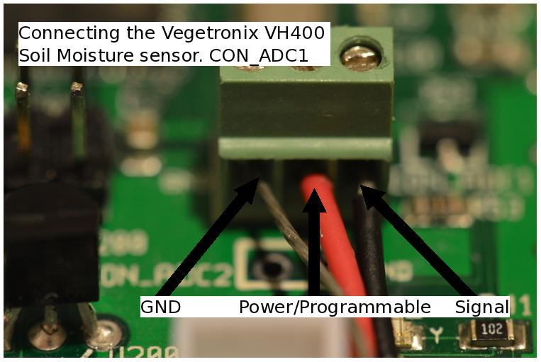
Soil moisture and water level sensors that give an analog output can be connected to any of the analog inputs CON_ADC1 or CON_ADC1. The CON_ADC1 has an extra pin for programmable power. The sensors power is controlled by the MCU. The idea here is to power up the sensor only when it's needed. This to minimize the power used and maximize battery lifetime. Programmable power is available on CON_ADC1. It enables the power pin on CON_ADC1 one second before reading the analog signal this to stabilize the electronics before reading he actual data. There is an debug option to verify when power is enabled. See D_PWR_1 which turns the red LED on when the power is on.- Below is the wiring for Vegetronix VH400 soil moisture sensor.
<
- Below VH400 soil moisture sensor.
<
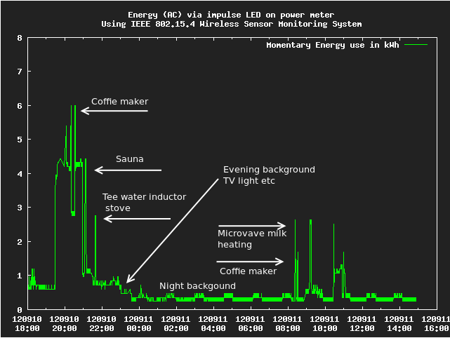
Project and Examples: Electricity use via power meter LED
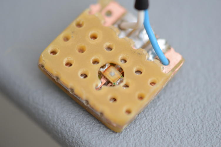
See the section regarding comparator and phototransistor. The photodiode was soldered to a veroboard in a sandwich contruction to eliminate background light and cables connected to 1206 footprint on the PCB. Attached to the power meter with adhesive tack.
![]()
NOTE. The phototransistor back side was covered with black glue to avoid ambient light.
Also the phototransistor PCB needs a comparator on the node PCB. See picture.
Below is the result commented gnuplot of data collected via the phototransistor and comparator to the P1 pulse input. This power meter gives 1000 pulses/kWh plot is calibrated to kW. One should note that reading a LED is a tricky process avoiding background light etc. Better to use the S0-interface on P0 input if possible.
Project and Examples: Electricity use via S0 on power meter
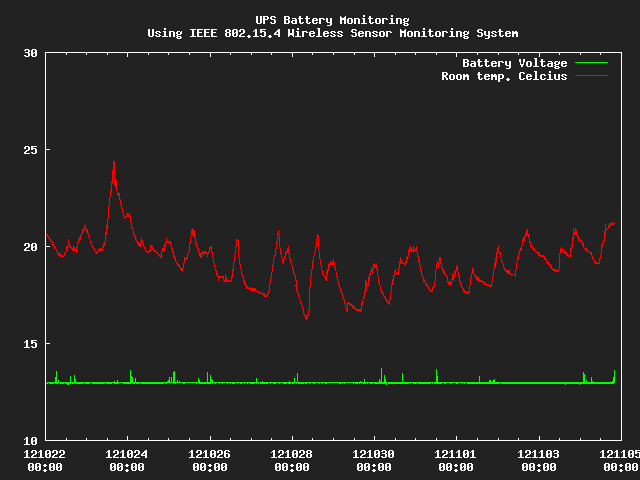
Project and Examples: UPS and battery monitoring
The mote is designed to measure the voltage to regulated power. Using this parasite power option it's very easy to monitor battery and UPS. Below a lead-acid battery for low-power server is monitored.
Project and Examples: Barometer I2C Module
There are relive cheap and accurate pressure modules to make an versatile barometer or altitude meter. Check out the Bosh BMP085 specs. It has I2C communications. There are modules to buy. Here we need some soldering skills to replace the humidity sensor at rear of the PCB. Also the battery holder is removed to make a robust mounting for the module. Custom firmware support for BMP085.
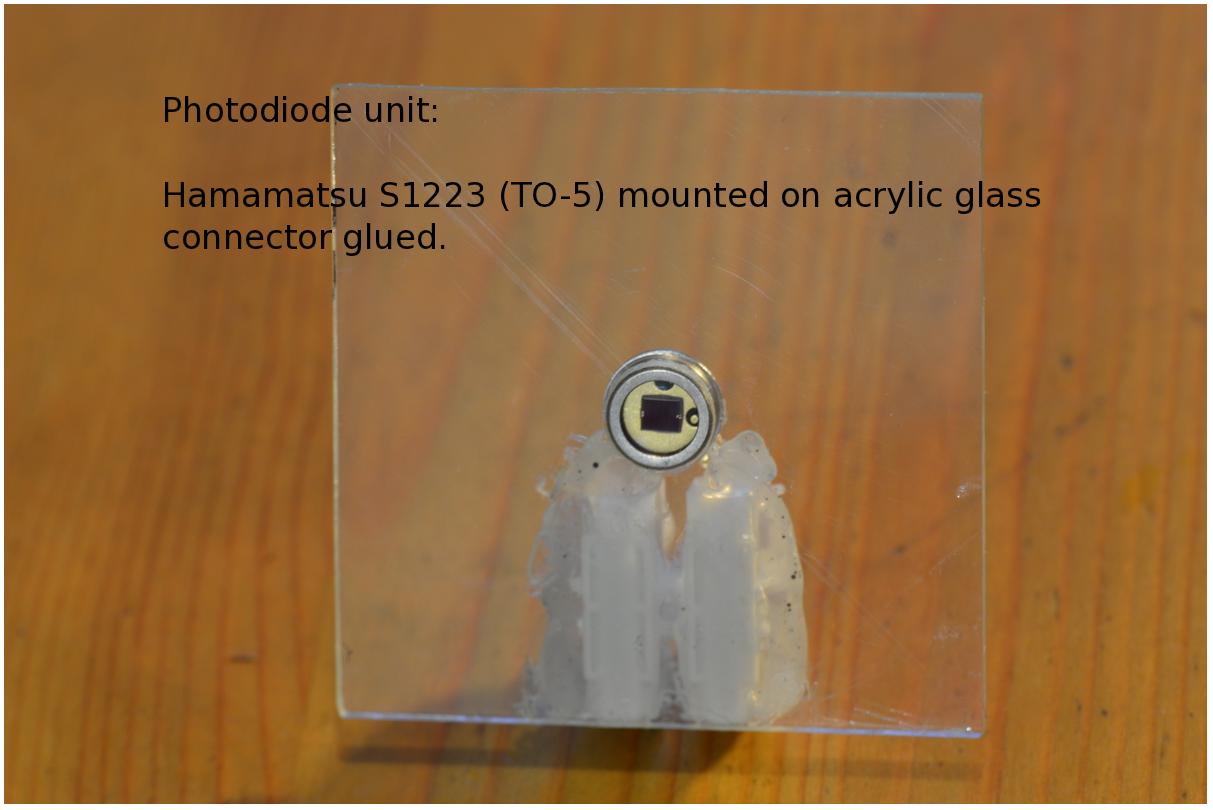
Project and Examples: Light measurement and pyranometers
One can add photodiodes to the analog inputs. ADC1, ADC2 either soldering directly to the connector via a cable. Photodiodes comes in many footprints though-hole or SMD. Application also effects design. If monitoring ambient light a SMD diode most most likely be enough. For more pyranometer applications rugged photodiodes with larger exposed is better. Regardless of size most likely a shunt resistor will be needed to read photometric power and not open voltage. Shunt resistor must match the size of the photodiode. Some experimentation might need. See also the HOWTO section. Example with and an external photodiode for solar power monitoring:
Example with and an SMD for ambient monitoring:
The author has done some tests, yet without any usable results.
Project and Examples: Wind monitoring
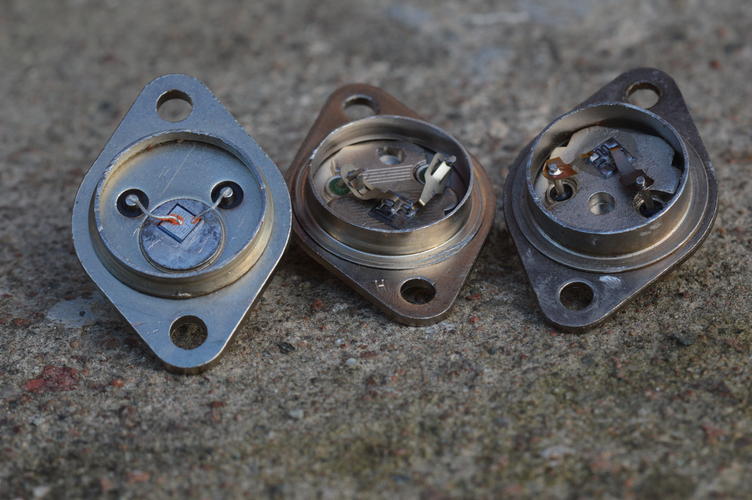
Project and Examples: Radiation measurements
It should be possible to use the pulse input to report, nuclear radiation for wireless typically alpha is interesting for radon monitoring. There have been interesting work how transistors like 2N3055 can be used as sensors
The author has done some tests, yet without any usable results.
Here is another alternative from teviso.com in Switzerland. Straight forward to connect the sensor node. Just three wires are needed. The low voltage version RD3024 should best to use.
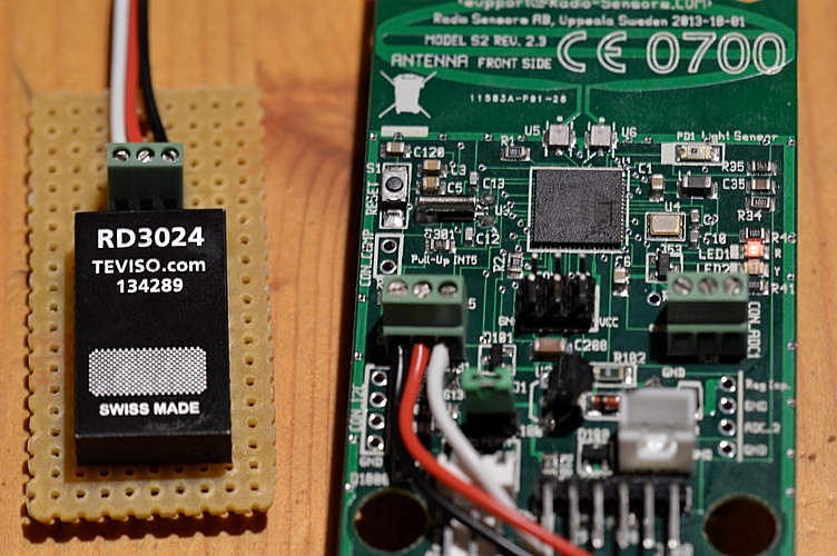
Product info via:
www.teviso.comScientific Gateway Effort
Project for common interface with authentication, meta-data, retrieval and presentation. The idea is to provide a common interface for multidisciplinary areas. Data collections and monitoring is one part of the work.
Product info via:
Sensordata collected via SSVL at KTH in StockholmFuture work
IETF is currently standardizing Constrained Application Protocol CoAP. This seems to be an important step for IoT. It would be nice to follow that path to have a very close or even use some parts of the standard for example payload encoding. But CoAP has today only mapping IP ipv4 and ipv6 but not the lightweight Rime protocol also used in Contiki. Nevertheless Contiki/Rime together with sensd is capable to form URI's and functionally work as a CoAP caching (due to asynchronous broadcast) server.
Real usage and reference installations
- Soil moisture, and soil temperature logging in Forcall, Castillon, Spain. Solar driven
with 3G gateway. Remotely logged.

- http://www.herjulf.se:8080/RPIQuerol/plots
See also the the Scientific gateway:
Known bugs and caveats
- P0, P1 only works. Sleep mode IDLE. See firmware command to force IDLE. (FIXED in Model S2)
References
- Adam Dunkels. Rime - a lightweight layered communication stack for sensor networks. In Proceedings of the European Conference on Wireless Sensor Networks (EWSN), Poster/Demo session, Delft, The Netherlands, January 2007.
- ATmega128RFA1- Atmel Corporationâ. [Online]. Available: http://www.atmel.com/devices/ATMEGA128RFA1.aspx. [Accessed: 21-February-2012].
- Atmel AVR2006: Design and characterization of the. Radio Controller Board's 2.4GHz PCB Antenna.
- [Add authors] Inclusive Ubiquitous Access - A Status Report, Africom, Younde, Nov 2012
- [SBN] IL2213 WSN-Projects Fall 2011. [Online]. Available: http://www.tslab.ssvl.kth.se/csd/files/wsn/index.html. [Accessed: 21-February-2012].
- The Contiki O. [Online]. Available: http://www.contiki-os.org/. [Accessed: 29-February-2012].
- IEEE 802.15.4. [Online]. Available: http://www.ieee802.org/15/pub/TG4.html. [Accessed: 21-February-2012].
- R. Olsson and J. Laas, Sensd. 20120610, Available at https://github.com/herjulf/sensd.
- draft-ietf-core-coap-12. [Online]. Available: https://datatracker.ietf.org/doc/draft-ietf-core-coap/. [Accessed: 15-October-2012].
- M. Kovatsch, S. Duquennoy, and A. Dunkels, A Low-Power CoAP for Contikiâ in Mobile Adhoc and Sensor Systems (MASS), 2011 IEEE 8th International Conference on, 2011, pp. 855-860, DOI:10.1109/MASS.2011.100.
- Future Technology Devices International Limited (FTDI), TTL to USB Serial Converter Range of Cables Datasheet. 20100902, Available at http://www.ftdichip.com/Support/Documents/DataSheets/Cables/DS_TTL-232R_CABLES.pdf.
- User Datagram Protocol. [Online]. Available: http://www.ietf.org/rfc/rfc768.txt. [Accessed: 26-May-2012].
- IANA: RFCUniform Resource Identifier (URI) Schemes. [RFC4395]
- 6lowPAN The Wireless Embedded Internet, Z. Shelby, C. Borman Nov. 2009
- 6lowPAN http://datatracker.ietf.org/wg/6lowpan/charter